
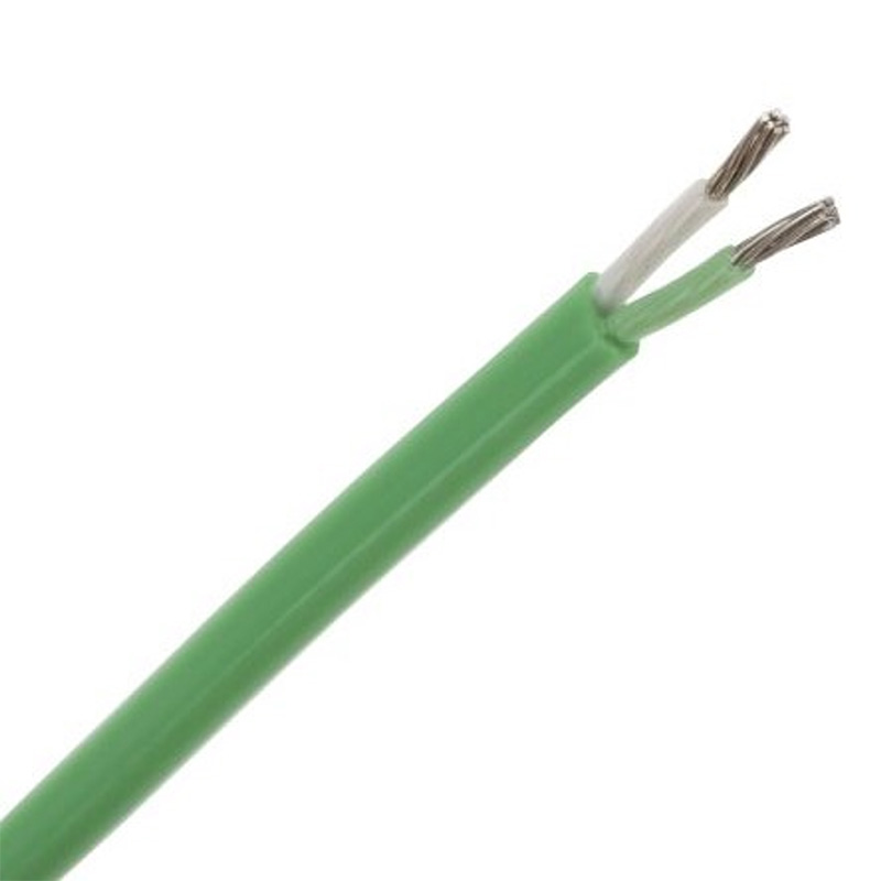
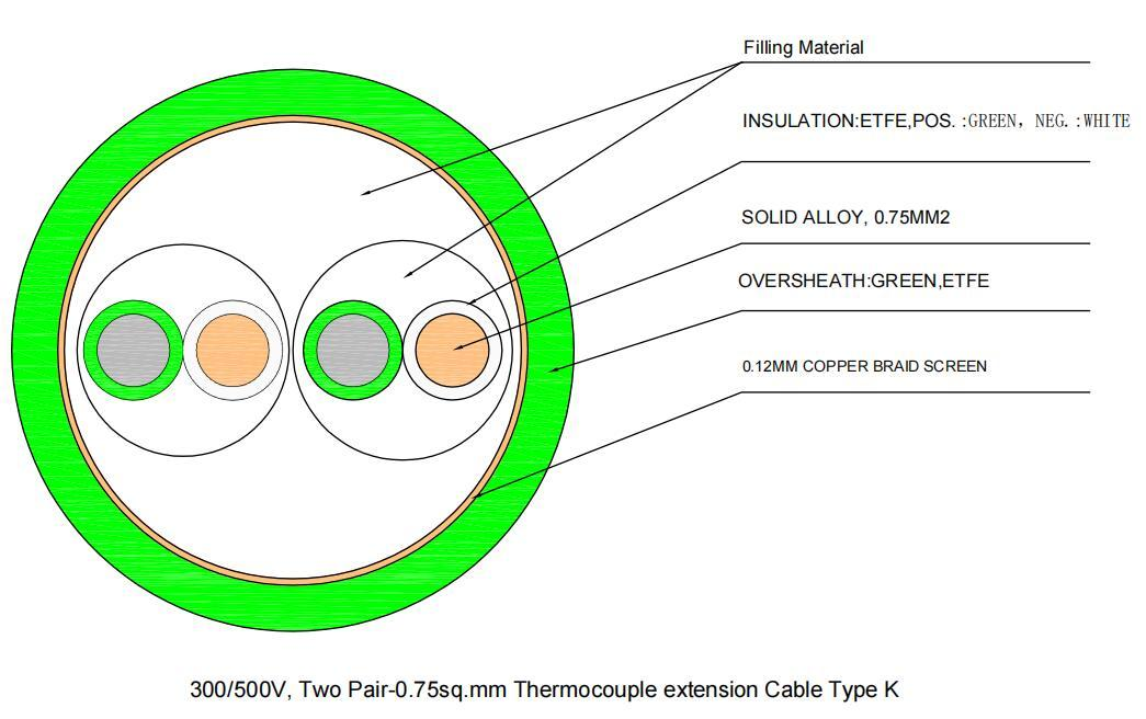
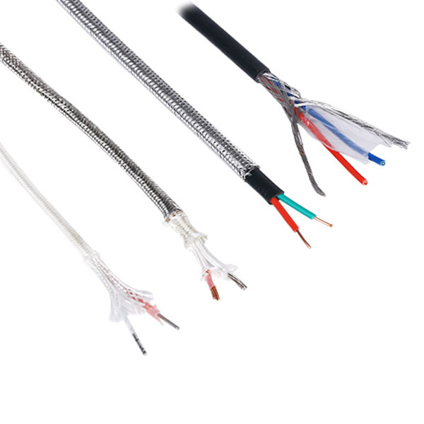
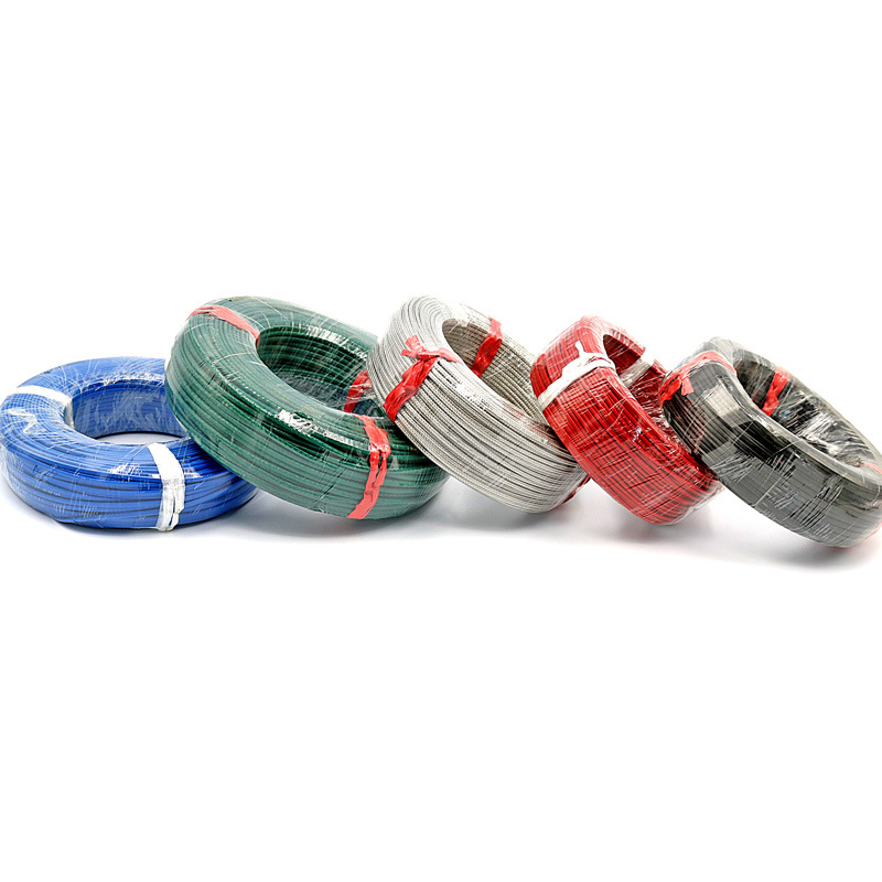
Thermocouple extension Cable Type K KX/ETFE/Copper braided shield OS/ETFE NICKEL- CHROMIUM/NICKEL AL Technical Requirements:

Contact: Mr Li
Phone: +86-18226665885
Tel: +86-0550-7788337
Email: sales@tiankangcable.com
Add: No.20# RenHe South Road,TianChang,AnHui Province,China
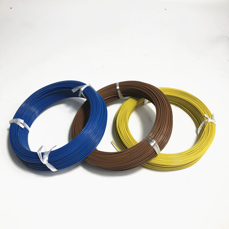
 Cable sales 2
 Cable sales 1